Unfortunately I've been busy with other things for the last months, so the KAPE 8bit -project hasn't gotten that many milestone progresses done as I would have wanted to. There was Christmas, and we moved to a new home, which is always stressful and a lot of work. Excuses, excuses - however, I've still done some bits of things. Not 8, but at least 3 things worth of mention. So let's call this the 3bit progress update!
MSB - Case (Prototype) Prototype
I've been envisioning the case as your basic computer-in-a-keyboard system. I did some mockup designs on Fusion 360, and originally planned to get it 3D-printed.

However, I had trouble finding a reasonably priced 3D printing/prototyping service, and IIRC it would've ended up costing over €100 euros to do a 3D printed case with the dimensions I was going for. I could probably optimize it somewhat, but I decided I'd do a prototype prototype case from KAPA-board, which we had lying around. KAPA-board is a 3mm thick foam board, that has glossy paper surfaces on both sides. It's similar to thick cardstock. Also the name fits so why not use it. :D

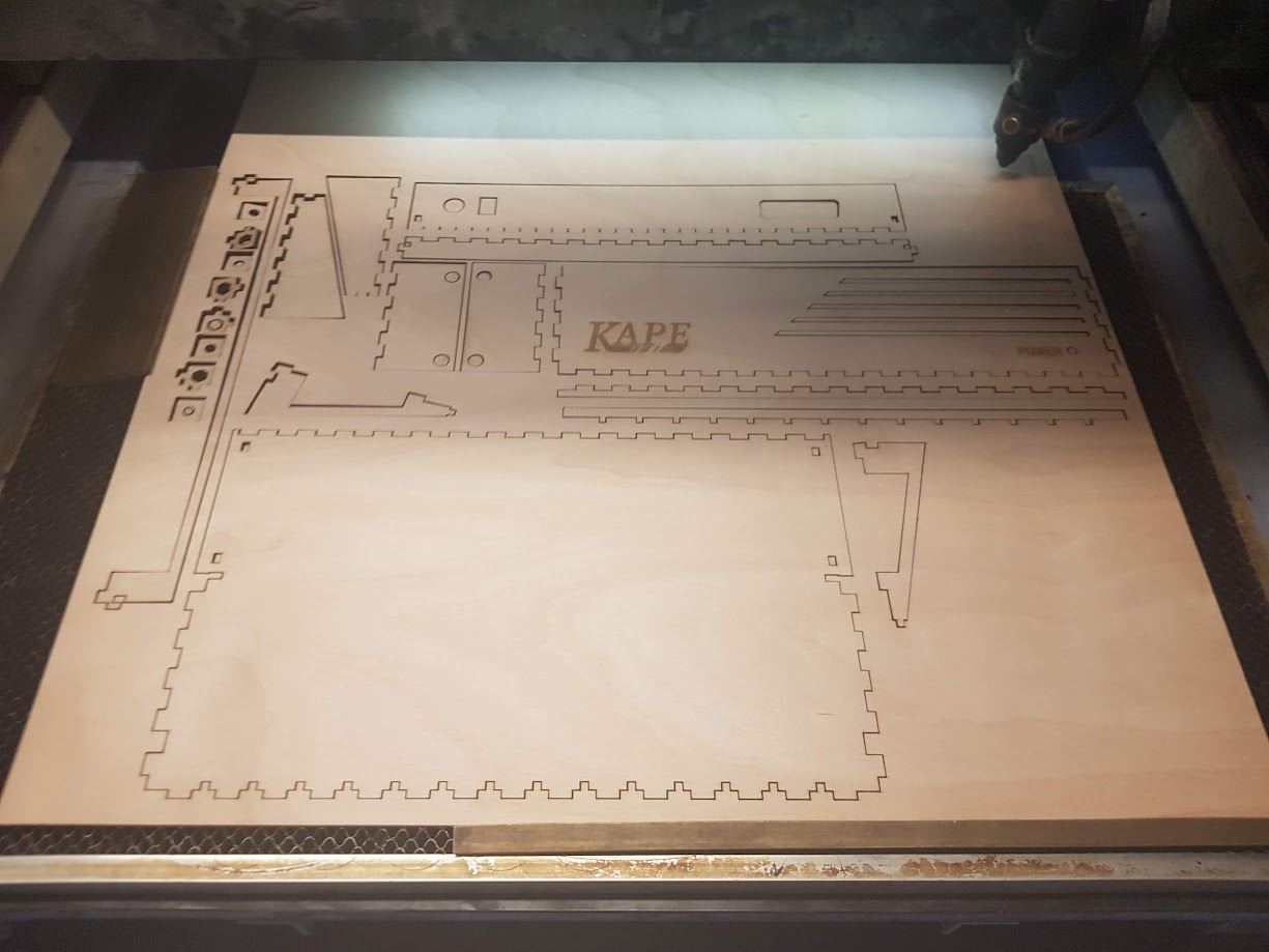
I used the Fusion360 model sketch dimensions to help me cut the board to size. I also got some 60% keyboard keycaps and gateron switches for the keyboard. For the faceplate I was going to do a laser cut order, but ended up with the same problem as with the 3D printing (namely, too expensive for a prototype prototype). The cheapest I could find was 30€ for a 1.5mm plywood with postage, so I might go for that at some point, but for now I opted to try out a (prototype) prototype [prototype] with KAPA-board yet again. Even though it's 3mm and the switches are meant for a 1.5mm faceplate, it's soft enough that if I make the holes a bit smaller than they need to be, they fit snugly and are hard to remove.

Stabilizers are still missing.
The soft KAPA-board was a bit too soft, and non-surprisingly it gives a bit of way in the center. However, I added some structural support to the case, so now it feels "rigid enough". No more sagging and only a small give when typing.

I'm quite happy with the "end result", as crummy as it is. I haven't really done any scientific measurements on it, but it should be big enough to house the components in PCB form. In breadboard form it's too small, but I think I can live with it by having the top lid open until I come up with a better solution to extend the size backwards. The prototype case is still missing some extra "smoothing" around the corners, closing the random holes in the intersection points, and giving it a coat of paint. It won't be pretty, but it'll be good enough. The keyboard itself is missing diodes and stabilizers, which have been ordered, but I should have all other components in stock (I was planning an ATmega16A for the keyboard controller and either a register chip or a SIPO or a FIFO chip to communicate the data the CPU).

Bit 1 - The CPU and System Circuit
I haven't much put my mind on the actual 8bit system part of the KAPE 8bit -design, and have been more consumed by the graphical capabilities of it. I had some time to fiddle with it though during these 2 months, and I had some AliExpress -bought R6502 chips to test out. So I wired up an $EA tester to give the CPU always a NOP, which should result in the CPU to just cycle through all the address space.
First things first, I needed a clock, so I made one with a 555, and using a potentiometer I can change the frequency from ~2 Hz to ~2kHz. This means I can adjust it so that I can visually debug the address bus with LEDs. After hooking up everything, I had to debug the thing for the next hour, as I had forgotten two things: 1) with NMOS processors, you can't run them too low a clock, or they lose their data 2) which way I wired the LEDs and which side is the MSB of the Address Bus.

Apparently the chip in question could actually be a G65SC02, which should be an earlier CMOS model, so it should be possible to run it in a lower clock (the datasheet doesn't support this idea though, as far as I understood it). And on the lowest setting, the address bus did behave somewhat irrationally. I however did find a higher clock, that was still debuggable visually and manually - once I figured out the correct LEDs I needed to be monitoring - that seemed to have gone through the correct restarting procedure and also cycled the address correctly. I think it was somewhere around 30 Hz.
After needing to up the frequency to get a correct restart procedure, I'm not that trusting that the chip works correctly with low clocks at all. So, I went ahead and bought a proper, original, modern W65C02S chip from Ebay. This came straight from UK, cost a bit more and had a bit higher postage, but apparently the seller is a trustworthy chip-seller: https://www.ebay.com/usr/toucano76 NB. Not an endorsement, just linking to where I bought the chip I believe is original and new.

Next up for the system/CPU design is to add a 64K memory chip, and a way to fill that memory chip with program data. I had an idea of adding 2K ROM chip that used either a 6522 or a 6551 to read memory data from either SD card or UNO connected to a PC as a serial link, but my 2K ROM chip still hasn't arrived, so I'm trying to setup a system that tristates the Address Bus from the 6502 (easy with the W65C02S) and keeps it reset, fills the 64K memory, re-enables the Address Bus for 6502 and then starts it. So, basically I'll use a UNO to write from PC to the memory straight.
This will most probably be the next exciting update - at this point it's starting to look and feel more like a computer, so I'll also most probably write a more detailed write-up on how I handle the current idea for testing code upload.
LSB - Squeezing Everything Of Kape GPU
Least bit last - I managed to squeeze a 64x24 (512x192) 16 color text mode out of the KAPE GPU and output it to PAL RGB. And it didn't look half bad! This should be possible to be extended to a 80x25 16 color text mode, as the timings are basically the same, and the extra memory usage doesn't really break the (memory) bank.

However, doing this (and the honorably mentioned below), resulted in me realizing that I'm getting a huge feature creep in my GPU right now, and it's hindering my progress on the whole system. So, I've decided to double down on the original specifications I made for the GPU, at least somewhat.
- Four modes
- 32x24 16 color text mode
- 256x192 tiled/sprite mode
- Combined Mode 1 and Mode 2
- 128x96 Lores streaming framebuffer mode
- Simple CMDQ FIFO communication with the CPU, read-only
- No interrupts etc. Timing done separately on the CPU side, and frame refreshes are independent of CPU speed or timing.
- Only output is RGB SCART for PAL
The rest of the features I've been wanting to do - composite out from RGB out with MC1377P or AD72x, 64x24 text mode, 40x25 + 80x25 text modes, etc. - will have to wait KAPE V2 or V3 or even V4. Also I just got a STM32F411CEU6 (aka Black Pill V2) from WeAct a while a go, and I was thinking of possibly using it's higher memory and DMA capabilities and faster clock speeds to do a single module GPU, just add some support chips around it to interface the 6502 and have a socket to put it in and done. Working with this idea is put on hold until future version, like the other feature creep ideas, though.
Bit ?? - Honorable Mention - Streaming Lores
Last, but not least (well, actually, yes least, this is only worth mentioning because I find it cool, but it's not useful to the project in any way). SO. I did a thing. With graphics Mode 4, the Streaming Lores mode, I realized I could push pixels from the PC out to the KAPE GPU. So I made screen capture program with C# using Imaging API - Graphics.CopyFromScreen(), Windows Graphics Capture API could be faster but this was easier to implement - resized it to 128x96 and piped it to a dithering library, and pushed the pixels out through USB Serial to an UNO and from there through a PISO chip to the CMDQ FIFO in the KAPE GPU and from there to a CRT as per normal.
I gotta say, playing modern games with a Retrofier™ (not a real trademark) was actually quite funny. I had some performance issues at first, but after making the whole thing on the PC side multithreaded with more processes to capture, resize and dither the screen, and some massaging with the serial output and UNO code timings, I managed to saturate the uplink and got ~27 fps.
Alright, that's an update for the last two months. Next plans with KAPE is most probably the CPU and System stuff, filling memory, adding ROM, SD cards, finishing keyboard, finishing case prototype, and lastly, designing the schema and PCBs for both GPU and CPU. Lots to do but I feel like I've made some progress too in these > 6 months.
Have a retro time and see you in the next post!